Solutions
Biogas plants and agricultural businesses produce large amounts of fermentation residues, manure and other liquids that are high in organic matter. These substances are rich in nutrients and are therefore essentially valuable fertilisers. However, their high water content increases their volume and weight considerably, leading to high transport and storage costs and CO₂ emissions. At the same time, the heterogeneous nature of the nutrients makes precise application in accordance with fertiliser legislation difficult.
The solution lies in reducing the volume of waste and recovering its nutrients. This means fewer transports, lower emissions and significant cost savings. At the same time, several valuable products can be created and returned directly to the agricultural cycle. By using sulphuric acid in a vapour scrubber, the ammonium nitrogen contained in the substrate can be bound to an ammonium sulphate liquid (ASL). This is important because unbound ammonium can escape as toxic and climate-damaging ammonia when stored unsealed or applied to land. However, in the form of ASL, the concentrated nitrogen can be applied precisely and forms a valuable product. In addition to ASL, evaporation produces a nutrient concentrate with a low water content. Reduced by 80%, this concentrate is easier to store and transport, and can be used specifically for soils with a high phosphorus and a low nitrogen requirement. The odourless distillate produced can be discharged or reused as process water.
For over 25 years, MKR has been developing innovative solutions for the treatment of liquid waste in industry and agriculture. As climate protection, resource conservation and land scarcity become increasingly important, technologies that reduce waste volumes and generate valuable by-products are coming to the fore.
The three automated evaporator systems from MKR Cleanwater are key to this:
- Thermal evaporators
- Hybridsystems with heat pumps
- Electric MVR evaporators
Thermal Evaporators
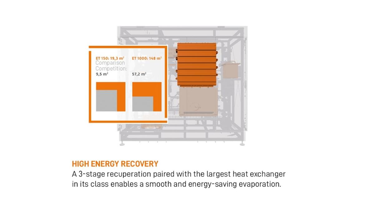
Our thermal evaporators use waste heat from biogas or combined heat and power plants to efficiently concentrate organic residues, such as fermentation residues or manure. This process is based on the principle of evaporation under vacuum, which significantly lowers the boiling point of the water within the medium. In the first evaporation stage, heat from a heating circuit is fed into the medium, heating it and generating water vapour. In the second stage, the pressure and boiling temperature are both lower. This enables the steam from the first stage to heat the fermentation residues in the second stage. Thus, a large proportion of the heat can be used multiple times.
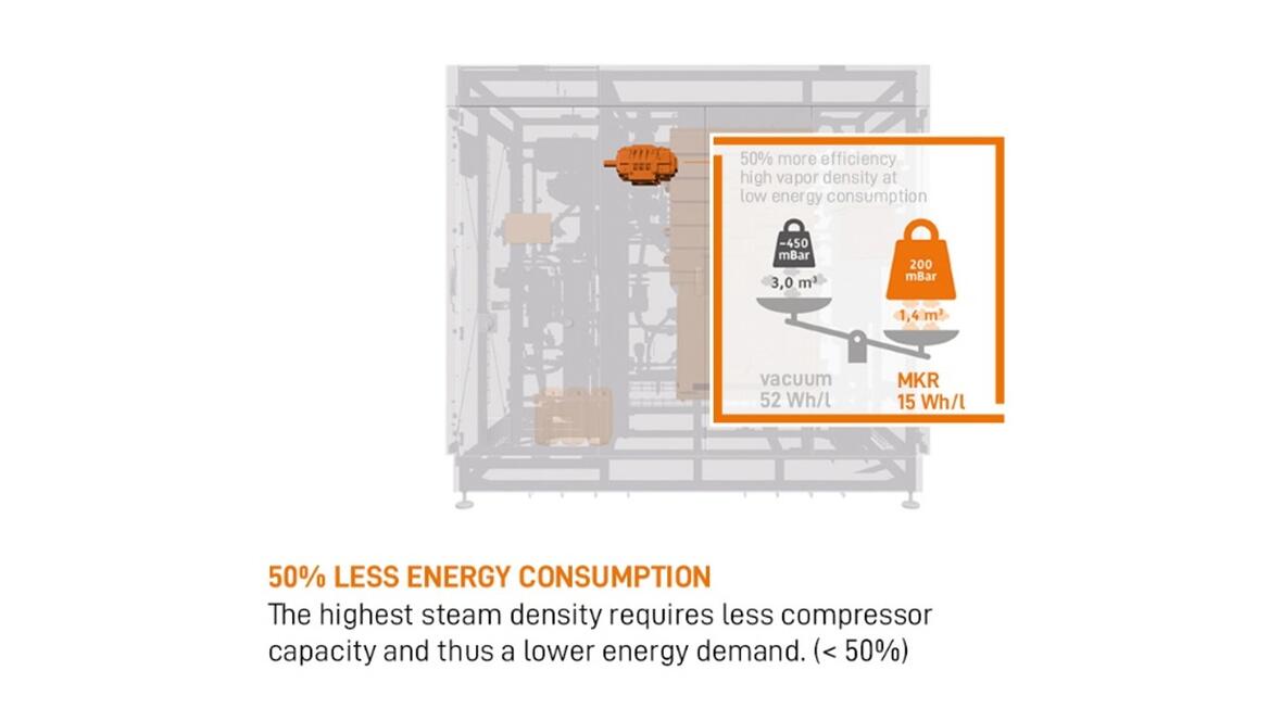
This process can be repeated three times in total. A four-stage system can therefore achieve an efficiency of up to 4.4 litres of distillate per kilowatt hour of thermal energy. In comparison, evaporation without a vacuum and heat recovery yields only around 1.2 litres per kilowatt hour.
The added advantage of lowering the boiling temperature is that heating below 65°C is particularly gentle on the material. Direct evaporators are ideal for locations with continuous waste heat and contribute to virtually climate-neutral processing by making use of existing energy sources.
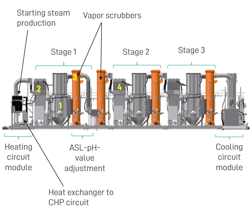
Operating Principle
Heating circuit and evaporation stage 1:
A starting steam of approx. 70°C is produced under vacuum. This starting steam is directed to the heat exchanger (2) of the first evaporator stage.
The digestate is in the process tank (1) and is circulated over the heat exchanger (2) with a pump. In the heat exchanger, the start steam heats the digestate, condenses and is fed back into the heating circuit module.
vapour scrubber:
The vapour (from the digestate) that has now been produced in evaporator stage 1 is fed through the vapour scrubbers (3). Here, the ammonia contained is bound with sulphuric acid and pumped out of the plant as mineral fertiliser ASL (ammonium sulphate liquid). After the vapour scrubbers, the vapour is fed to the heat exchanger of the 2nd evaporation stage (4). Here, this 1st stage vapour heats the digestate of the second evaporator stage, cools down, condenses and can then be pumped out of the plant as liquid distillate.
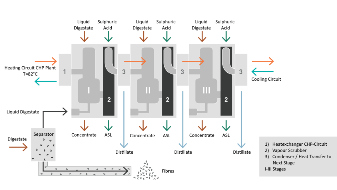
Evaporation stage 2, further stages and cooling circuit:
The same process now takes place in the second evaporator stage as in the first evaporator stage. Water vapour is produced from the fermentation residue, washed in the vapour scrubber and this water vapour releases its heat energy at the heat exchanger of the next stage and condenses out. This heats the fermentation residue of the next stage again.
After the last evaporation stage, the cooling circuit module follows. Here, the steam from the last evaporator stage is cooled. The steam condenses into distillate and can be pumped out of the system.
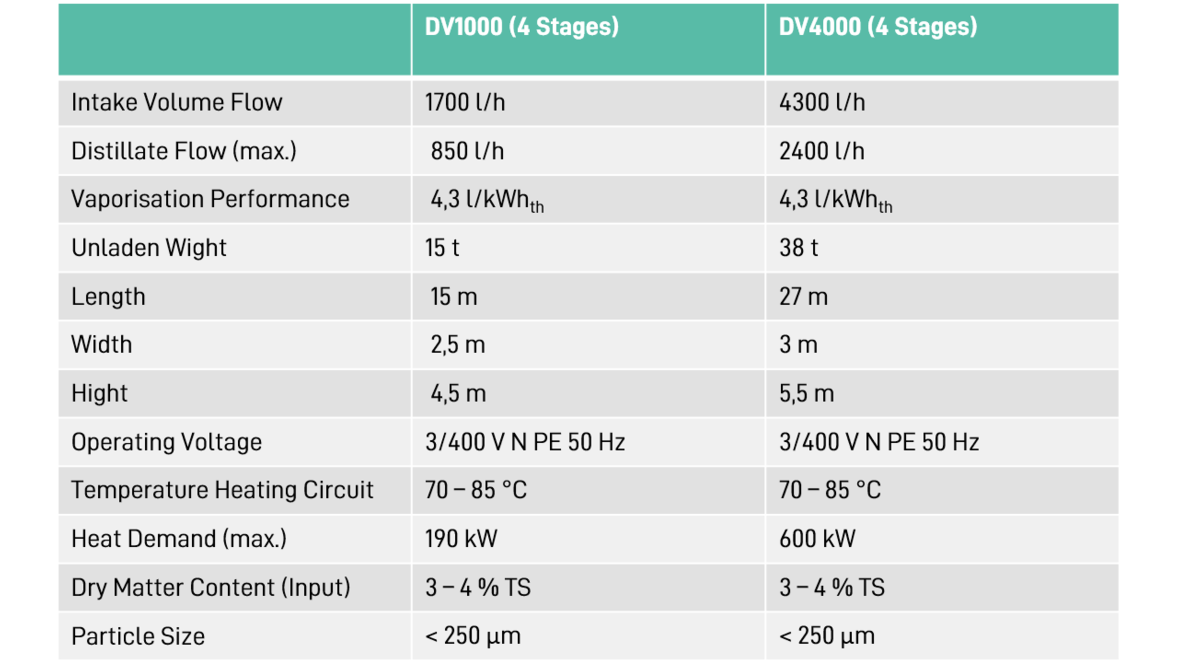
Operating Data
Various evaporator systems are available for different volume flows and with two to four stages.
Hybrid Systems with heat Pump
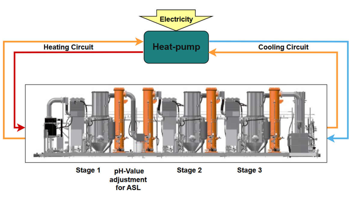
The thermal evaporator can also be fitted with a heat pump. This is particularly useful in locations where the heat supply fluctuates. When there is insufficient heat available, the heat pump can be used to raise the waste heat from the evaporator back up to the initial temperature.
Electrical MVR-Evaporator
Our electric evaporators operate using the principle of mechanical vapour recompression, making them particularly suitable for use with media containing low levels of solids. During this process, the produced water vapour is compressed mechanically, which causes its temperature to rise. This heat is then used to reheat the medium, creating a closed cycle. This enables the evaporators to achieve a very high efficiency of up to 25 litres of distillate per kilowatt hour of electricity.
The compact, modular design of the system allows for easy extension without altering the technology itself. Electric MVR evaporators are therefore ideal for decentralised plants without a heat source, and they can be operated using renewable electricity, making their carbon footprint particularly positive.
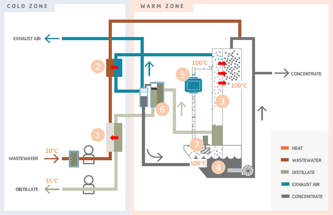
Operating Principle
The digestate or slurry goes through three heat exchangers (1,2 & 3) to the process tank (4). Here it is circulated and heated by the main heat exchanger (3).
The steam (7) is compressed (5) (approx. +200mbar) and has now a temperature of about 106°C. On contact with the main heat exchanger (3) the steam condensates and becomes distillate (6).
For media containing ammonia, a vapor scrubber is installed to remove ammonia from the vapor before condensation at the heat exchanger (3).
The exhausted air (via heat exchanger 2) and the distillate (via heat exchanger 1) leave the evaporator. The concentrate (from tank 4) is pumped regularly out of the machine.
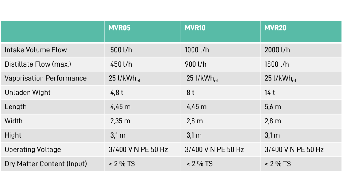
Operating Data
The MVR evaporator is available in five different sizes.
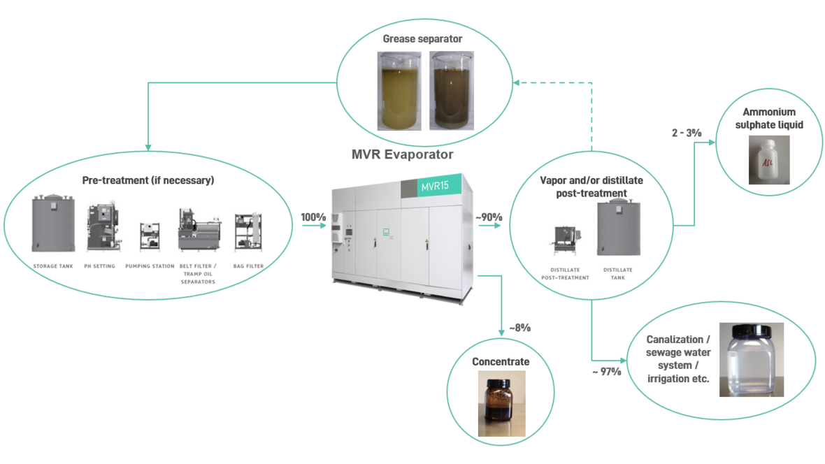
Suitable for various media
In addition to fermentation residues and slurry, many other liquid wastes can be processed. Leachate and wastewater, flotate, grease trap media and percolate are also suitable and have great potential for resource recovery.
The processing of substrates for biogas plants can also take place before fermentation. Concentrating pig manure directly at the barn significantly reduces transport and storage costs.